The RO Membrane Explained: Construction, Rejection Rate, and Lifespan
A precise look at how TFC RO membranes are constructed, what rejection rate actually measures, and the specific conditions — chlorine, scaling, fouling — that shorten membrane life. Includes Indonesia-specific context.
The RO membrane is the only stage in a reverse osmosis system that actually removes dissolved contaminants. Every stage before it — the sediment pre-filter, the activated carbon block, the booster pump — exists to deliver water to the membrane in a condition it can handle. Understanding what the membrane is, how it is built, and what degrades it explains the logic behind every maintenance interval in the system.
What a TFC membrane is
The vast majority of domestic RO membranes sold today are thin-film composite (TFC) membranes. The name describes the manufacturing approach: multiple distinct polymer layers bonded together, each contributing a different property to the finished film.
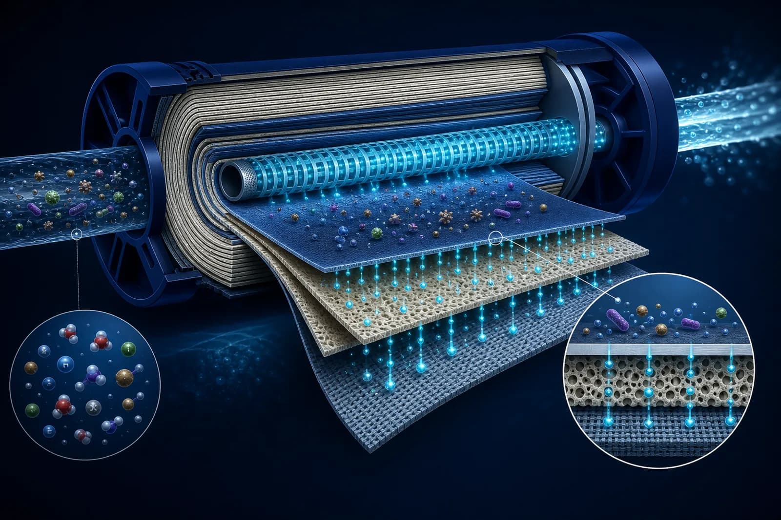
A TFC membrane has three main layers.
The active polyamide layer is the barrier that performs the separation. It is an extremely thin aromatic polyamide film — indicatively in the range of 0.1 to 0.2 microns, though precise values vary by manufacturer and grade. Effective pores across this layer are roughly 0.0001 micron (0.1 nanometre) — smaller than hydrated ions, which is why dissolved salts cannot pass through. This is the layer the specification figure "0.0001 micron filtration" refers to.
The polysulphone support layer beneath the polyamide provides mechanical stability. The active layer is too thin to hold operating pressure on its own; the polysulphone gives it a rigid substrate without blocking water movement through its own larger-pore structure.
The polyester base fabric is the structural backing — a woven or non-woven sheet that holds the stack together and allows the finished membrane to be wound into a spiral configuration.
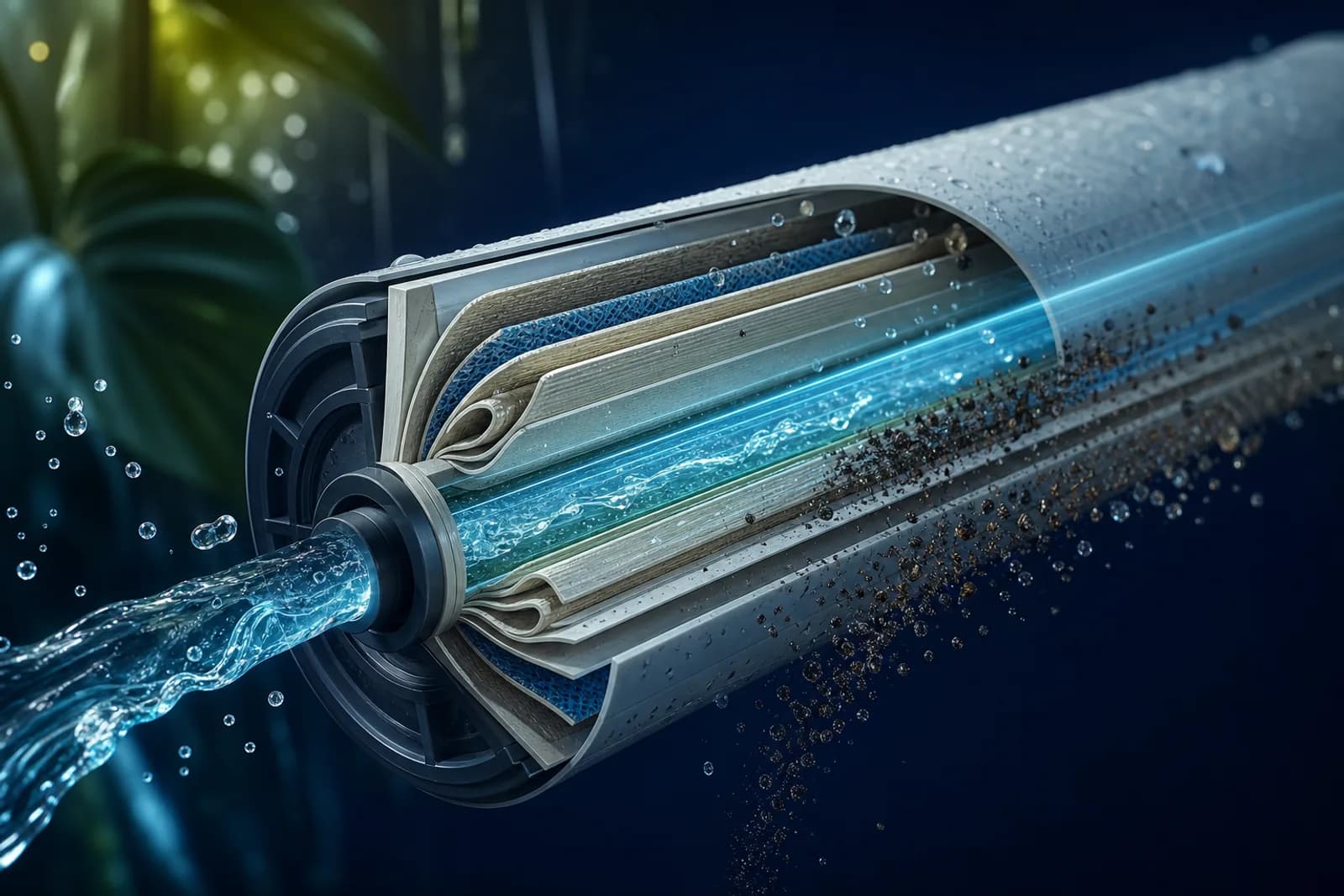
The spiral-wound design is the standard for domestic RO. The flat membrane sheet and a mesh spacer are rolled around a perforated central tube, like a scroll, and sealed at the edges. Feed water flows along the outside of the spiral; permeate passes through the membrane and migrates inward through the spacer to the central tube; reject exits at the far end. This geometry packs a large active membrane area — commonly in the range of 3.6 to 5.5 square metres for a standard 75 GPD domestic cartridge, depending on format — into a compact cylinder.
Rejection rate: what it measures and what it does not
Rejection rate is the standard performance metric for an RO membrane. It expresses the percentage of a target dissolved substance that the membrane removes from the feed water. A membrane rated at 97% sodium chloride rejection passes 3% of the salt in the feed through to the permeate.
The rating is measured under controlled laboratory conditions: 25°C feed temperature, 250 ppm sodium chloride solution, 150 psi (about 1 MPa) operating pressure, and a specific recovery rate. Real installed conditions deviate from all four variables, so the rated figure is a benchmark rather than a field guarantee.
Several variables affect real-world rejection:
Feed water temperature. Higher temperatures increase membrane permeability — water molecules move through more easily, but so do some dissolved substances. A membrane running at 30°C (typical for uninsulated pipe runs in a tropical Indonesian home) will commonly show modestly lower effective rejection than the same membrane at the rated 25°C. The effect is real but not dramatic under normal domestic conditions.
Operating pressure. Higher pressure increases the driving force for water across the membrane, improving rejection because the relative flux of water versus dissolved substances rises. Under-pressured systems — common when PDAM supply is weak and the booster pump is undersized — show degraded rejection.
Recovery rate. The more water you extract as permeate, the more concentrated the reject stream becomes, and the higher the osmotic back-pressure the membrane must overcome. At high recovery, the concentration gradient drives some solutes through that would be blocked at lower recovery. This is why manufacturers specify a maximum recovery rate.
Feed TDS. For high-TDS feeds — borehole water with heavy mineral load, or coastal groundwater with saltwater intrusion in areas like Jakarta's north coast — osmotic pressure is higher, meaning the effective rejection at a given pump pressure may be lower than the spec sheet assumes.
A practical check: measure TDS at feed and permeate output. If the ratio gives a rejection rate well below the membrane's rating under normal conditions, the membrane may be fouled or aged — or the pre-stages are failing to protect it.
What a realistic lifespan looks like
A new, well-protected TFC membrane in a properly maintained RO system commonly lasts two to three years. Some manufacturers quote nominal lifespans of five years or more, but these figures assume pre-filter stages are replaced on schedule and feed water quality stays within the membrane's rated range throughout.
In Indonesian conditions, several factors push toward the shorter end of any stated range.
Tropical ambient temperatures. Warm water reduces viscosity and increases flux, placing a higher sustained load on the active polyamide layer. The effect is gradual, but a membrane running year-round at 28–32°C is working harder than one rated at 25°C.
Sediment-heavy feeds. After a PDAM supply interruption, or in areas where the piped network is old, turbidity spikes are common. If the PP sediment pre-filter is overdue for replacement, fine particles reach the membrane surface and partially block the feed spacer — a condition called fouling that raises operating pressure and accelerates wear.
High-TDS groundwater. Sumur bor (borehole) water in Jakarta's peri-urban areas can run to several hundred ppm TDS, sometimes above 500 ppm in coastal zones. The membrane works against a higher osmotic gradient, and the more concentrated reject stream increases the risk of scaling over time.
Chlorine exposure. This is the most common cause of early membrane failure in chlorinated municipal supplies. PDAM water in Indonesian cities carries residual chlorine for disinfection — commonly in the range of 0.2 to 0.5 mg/L at the tap, though this varies by city and utility, and spikes can be higher. Even brief, low-level chlorine exposure degrades the polyamide active layer over time. Sustained exposure destroys it. The pre-carbon stage exists specifically to adsorb chlorine before it reaches the membrane; if that cartridge is left past its service life, chlorine breaks through.
The specific degradation pathways
Knowing what degrades a membrane explains why the maintenance schedule is not arbitrary.
Chlorine and chloramine oxidation. Free chlorine and combined chloramines both attack the amide bonds in the polyamide active layer, breaking down the tight polymer network that creates the membrane's rejection capability. Initial signs are a rise in permeate TDS — rejection degrades before flow rate is noticeably affected. By the time you notice a change in taste, damage has been accumulating for some time. Chloramines, used as a secondary disinfectant by some utilities, are not removed as readily by standard activated carbon block as free chlorine is; catalytic carbon is more effective for chloramines, and prolonged exposure to either oxidant without adequate pre-carbon protection will damage the membrane.
Biological fouling. Bacteria and biofilm on the membrane surface reduce effective flux and can produce organic acids that further degrade the polyamide. A pre-carbon stage that has exceeded its capacity can shed bacteria rather than removing them, feeding directly into the membrane.
Mineral scaling. Calcium carbonate, calcium sulphate, barium sulphate, and silica can precipitate on the membrane surface when the reject stream becomes concentrated beyond the solubility limits of those minerals. Scaling is most common at high recovery rates and with hard feed water. A scaled membrane shows declining permeate flow with little initial change in rejection, progressing to both reduced flow and reduced rejection as scale physically blocks and then breaches the active layer.
Physical damage. Pressure spikes — from a pump startup surge or a sudden valve opening — can cause mechanical stress on the membrane. More commonly, a failed or missing O-ring allows unfiltered feed to bypass the membrane entirely, which produces a performance collapse sometimes mistaken for a failed membrane.
Reading the signs
A healthy RO membrane keeps product-water TDS consistently low relative to feed TDS. Monthly spot-checks with a handheld TDS meter are the simplest way to track membrane condition over time.
Watch for:
- Rising product TDS at stable feed TDS — the clearest indicator that rejection is degrading. A membrane in good condition on typical PDAM feed should produce permeate well below 50 ppm; a worn or fouled membrane may drift above 100 ppm.
- Falling permeate flow at unchanged pressure — points toward scaling or biological fouling on the membrane surface.
- Both rising TDS and falling flow simultaneously — points toward severe fouling or physical damage.
Rising TDS alone, without flow change, is more often oxidative degradation (chlorine damage) than fouling. Falling flow alone, without initial TDS change, is more often scaling. These patterns are not diagnostic certainties, but they direct the maintenance conversation usefully.
The pre-stage connection
The RO membrane cannot protect itself. Its condition depends entirely on what the upstream stages do — or fail to do. A carbon block past its capacity sends chlorine into the membrane. A sediment filter running past its replacement interval lets particles into the feed spacer. A pump delivering inadequate pressure leaves the membrane unable to reject efficiently.
This is the logic behind the asymmetric replacement schedule: sediment and carbon cartridges change every six to twelve months; the membrane, protected by those stages, can last two to three years or longer. Neglect the pre-filters and the membrane carries the full burden they were supposed to absorb.
The membrane is the most expensive individual cartridge in the system. Replacing the cheap upstream stages on time is the most cost-effective way to protect it.
Not sure which system fits your water?
Aright Marketing Indonesia can assess your supply and recommend the right Truliva system for your home or business in Indonesia.